
For a while I have been wanting to learn how to program ARM based microcontrollers. The motivation came from what seemed to be significantly more advanced microcontrollers at the same or even lower prices when compared to the the AVR based chips (ATmega328, for example). The learning curve kept me at bay though. There are so many things to consider: development environment, ease of programming, how to actually program the chip, etc. Exploring a bit I mainly tried two ARM based development boards: 1) STM32 and 2) SAM chips from Atmel.The ARM based microcontroller from STM32 that I used was the 'blue pill' in conjunction with the book 'Beginning STM32' by Warren Gay. I like this book and approach (which relies on the libopencm3 library) and I plan to return to this. The second approach used a development board from Sparkfun electronics for the ATSAMD21G and the book 'Atmel ARM Programming for Embedded Systems' by Mazidid, Chen, and Ghaemi. The book was a little dry at first (first edition I believe) but after reading through and trying the examples it began to grow on me. I appreciate the low-level programming offered in the book. When googling for examples on problems I had been finding it seems that most people use the Arduino IDE or the ASF. With my background in AVR and being more familiar with toggling bits in registers, the book's approach has made more sense. That being said, I would like to understand how these software frameworks are developed to simplify programming (through uses of classes for example... a subject that always seemed out of reach on the ATmega328 due to memory restrictions).
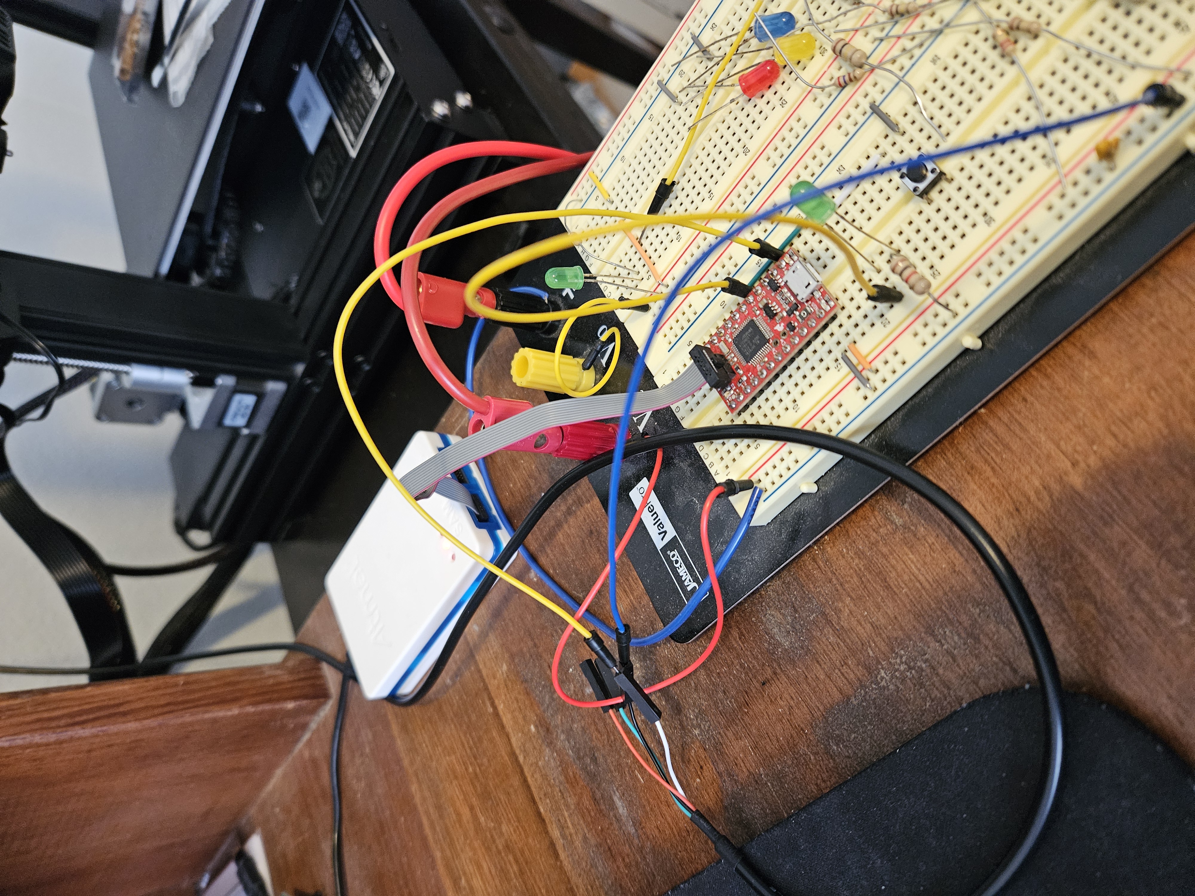
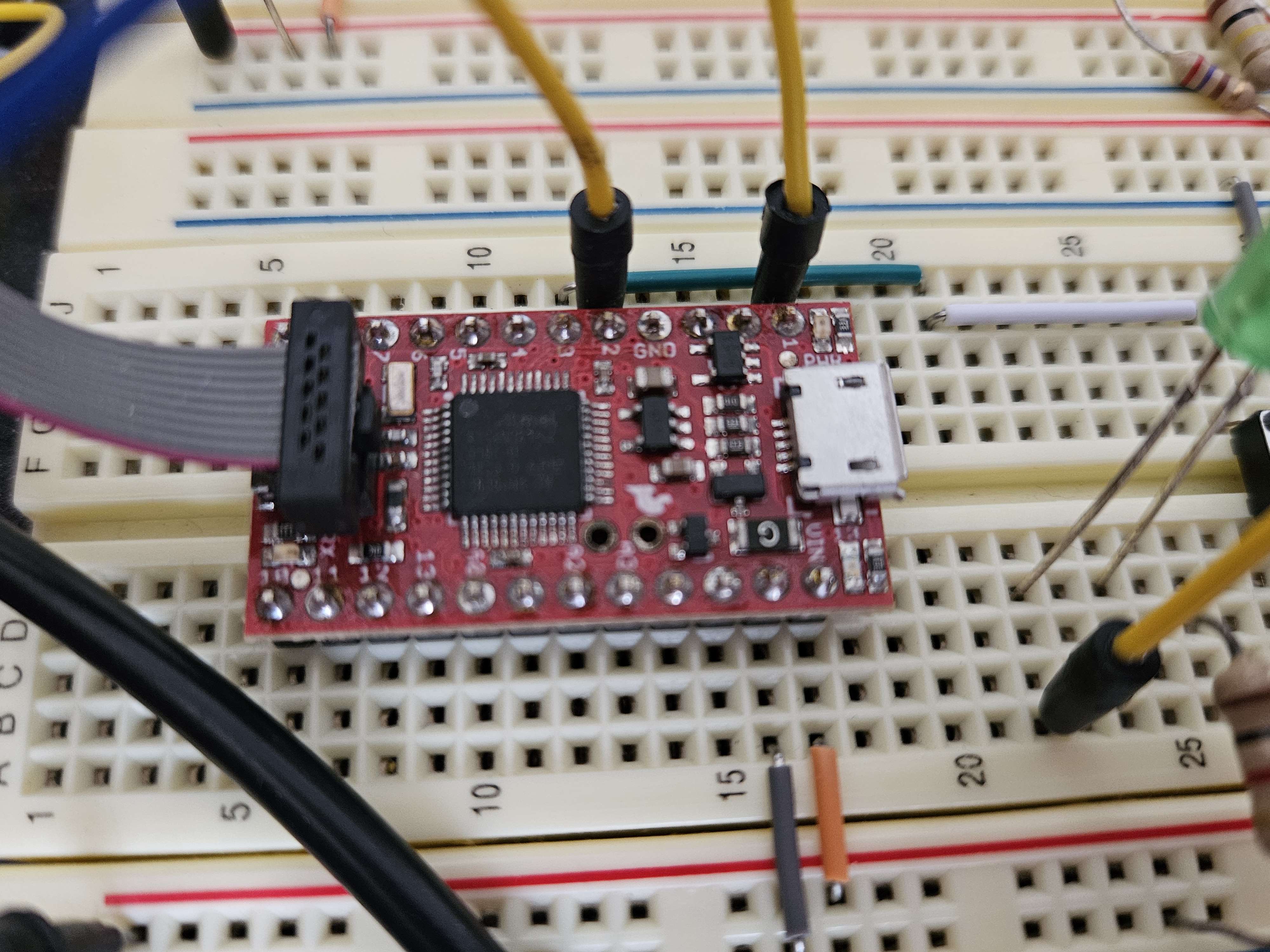
Finally, I want to note that I am always jumping between an IDE and text editor for development. Using sublime text with avr-gcc and Make worked well for developing AVR based designs but up to this point, I am not familiar enough with ARM based microcontrollers so having a development environment like Microchip Studio (formerly Atmel Studio) along with a proper debugger (I'm using Atmel ICE) has allowed me to more easily debug my programming mistakes. Pictures of the basic development environment are shown below. On the left, one can see how the Atmel ICE connects to the SAMD21G development board from Sparkfun. On the right, a close-up of the board connection is shown. Notice that the key on the cable is facing towards the chip with the red conductor closest to the camera. Again, the programming environment I am currently using is Microchip Studio. Below I am going to be posting notes that I find useful for programming these chips. Hopefully, I will also integrate this all into a project to showcase the learnings. It would be nice to circle back and ask the question, would this be easier with an STM32 approach (or other).


There's a lot more clocks with the ATSAMD21G when compared to the ATmegas. My current understanding is, upon reset, the ATSAMD21G uses the OSC8M internal oscillator for the GCLK0 (GCLK_MAIN) with a divisor of 8 to have a CPU and GLCK0 clock frequency of 1 MHz. The clock source and divisor can be altered by selecting registers from the main code. This means we don't have to deal with those fuses (or so I think).
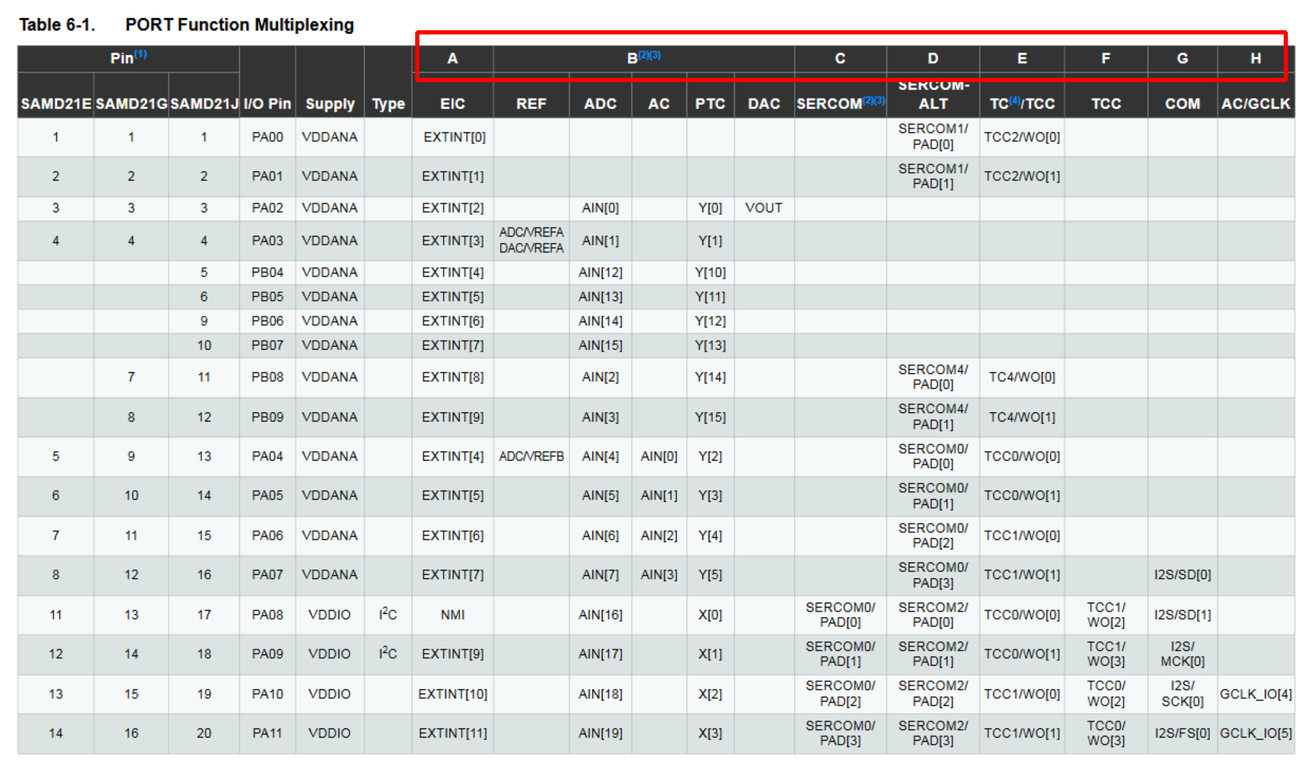
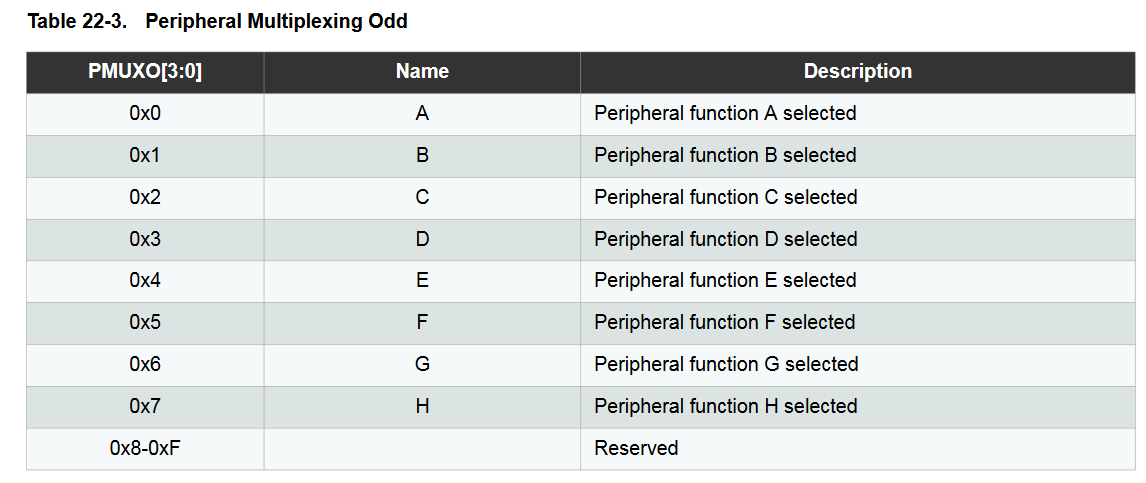
The SAMD21 allows many of the the pins of the chip to be configured to what the user needs. This is handy but can be confusing. How do you configure the pin for your needs? Say, for example, you want to set up the UART on PA10 (TX) and P11 (RX). Look at Table 6-1 below. I've highlighted a portion of the columns that correspond to the functions. So, if you want PA10 and PA11 to utilize the SERCOM peripheral (which the USART/UART is part of) you will have to set those pins to Function C. This function is called out in the PORT Register Summary later on in the datasheet, Table 22-3 (shown below). So you have to set PMUX Register for PA10 and PA11 to C which corresponds to writing 0x2 into the appropriate registers. So what are these appropriate registers? Well, if we are working in Microchip Studio we have available to us the sam.h header file which makes available to us a large number of macros, structures, etc. We want to configure the Port A which corresponds to REG_PORT_PINCFG0 and REG_PORT_PMUX0 but the sam.h header file only makes available the first pin. So, per the advice of Mazidi, Chen, and Ghaemi, set up an array of pointers that begins at the address, for each address:
unsigned char* ARRAY_PORT_PINCFG0 = (unsigned char*) ®_PORT_PINCFG0;
unsigned char* ARRAY_PORT_PMUX0 = (unsigned char*) ®_PORT_PMUX0;
We first need to tell the REG_PORT_PINCFG0 that we want to turn on the multiplexer. This is done by writing a one to the appropriate register for PA10 and PA11:
ARRAY_PORT_PINCFG0[10] |= 1;

ARRAY_PORT_PINCFG0[11] |= 1;
The index of the array is simply the pin that you are trying to configure, 10 an 11 in this case. The datasheet says that there are 32, 8-bit of the PINCFG registers so there is a one-to-one mapping. This isn't so with the PMUX. There are only 16, 8 bit registers. This means you have to figure out the index to use for the ARRAY_PORT_PMUX0 we created above. To simplify things I created the table below which just maps things out to allow one to look up the array index. For PA10 we look in the even column (lower 4-Bits) and see that PA10 maps to PMUX5. Further, for PA11, we see in the Upper 4 bits column that 11 also maps to PMUX5. So they both map to the same PMUX register but one is the lower 4-bits while the other is upper 4-bits. For function C (SERCOM) we need to write 0x2 in these registers:
ARRAY_PORT_PMUX0[5] = 0x02;

ARRAY_PORT_PMUX0[5] |= (1 << 5);
| PMUX | Upper 4 Bits Pin | Lower 4 Bits Pin |
|---|---|---|
| 0 | 1 | 0 |
| 1 | 3 | 2 |
| 2 | 5 | 4 |
| 3 | 7 | 6 |
| 4 | 9 | 8 |
| 5 | 11 | 10 |
| 6 | 13 | 12 |
| 7 | 15 | 14 |
| 8 | 17 | 16 |
| 9 | 19 | 18 |
| 10 | 21 | 20 |
| 11 | 23 | 22 |
| 12 | 25 | 24 |
| 13 | 27 | 26 |
| 14 | 29 | 28 |
| 15 | 31 | 30 |


Now the pins are ready to be configured for UART. Note: This method worked for me and relied heavily on Atmel ARM Programming for Embedded Systems which can be pretty clunky on how they configure registers. For example, setting the value of a register to a hex number. It's so much cleaner and easier to understand if you do bit shifts. Another clean way is using structures and bit fields which is possible with the sam.h header file (and everything else it includes). An example of using these structures is nicely demonstrated here: https://blog.thea.codes/reading-analog-values-with-the-samd-adc/. I started to use this approach and it is much simpler and has clarified my code and fixed some bugs I had. It is easy to bit shift into the wrong filed or confuse the hex value and binary equivalent.
The SAMD21G Cortex M0 comes with a 24-bit System Timer that can be used to schedule reoccurring tasks. It's simple to setup once you realize there isn't much to it, however, the lack of information in the datasheet is surprising. A nice review on setting the up the System Timer is given by SysTick and the SAMD21.
Just a reminder here for the pinout of this cable: USB to TTL Serial Cable.
| Pin (color) | Function |
|---|---|
| Red | 5 VDC |
| Black | Neutral |
| White | Rx of USB |
| Green | Tx of USB |
The first stencil was a 0.005 inch polyimide from OSH Stencils. I'm pretty sure I usually order 0.003 in stencils. The 0.005 in seems to leave too much solder on the pads and leads to bridging across the pins.
The heat gun was set to 320 C (seems that the display reads in centigrade) and with a thermocouple at the middle of the board with the heat gun about 2 inches from the board. The thermocouple read between 270 and 320 C.
With all the solder bridging between pins I tried to use a desolder braid but the braid I have was not effective. I ordered one that has flux included in the braid and some rosin flux that can "fix" the braid that I have now.